-
-
Single-phase IoT electricity meter(Type DDZY2397)
- Product introduction
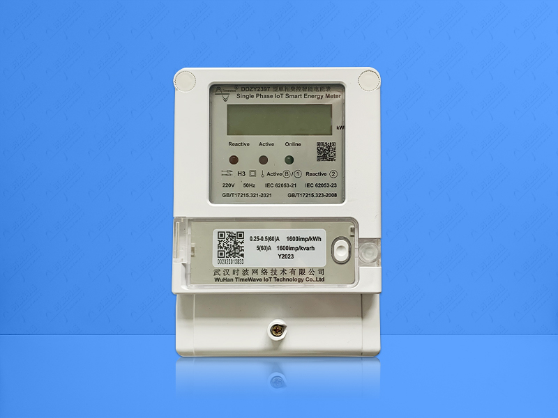
DDZY2397 single-phase fee controlled smart energy meter (single-phase IoT energy meter) is a fully digital smart energy meter developed by our company. It adopts SOC highly integrated chip and has the function of active electric energy measurement.
- Details
-
DDZY2397 single-phase fee controlled smart energy meter (single-phase IoT energy meter) is a fully digital smart energy meter developed by our company. It adopts SOC highly integrated chip and has the function of active electric energy measurement. There are also multiple functions such as online power display, intelligent anti-theft electricity, overload control, and remote centralized meter reading. The data is transmitted to the corresponding platform through the LoRaWAN/NB-IoT/Cat.1/ Bluetooth wireless network. It has high precision, low power consumption and good stability. It can be widely used in metering occasions of single-phase alternating current in cities, villages or factories.
Functions and Features
· The function of measuring forward active and reverse active electric energy, where the reverse electric energy is accumulated in the forward direction. It can measure, store and display the voltage, current, power, power factor, frequency and other operating parameters and status of the current electricity meter.
· Remote blackout and power transmission function: Power off command is issued through communication interface such as RS485 to cut off the user's load loop. Or issue a power transmission instruction to turn on the user's load loop.
· Active upload / bidirectional transparent transmission function. Actively upload the data to the corresponding platform through the LoRaWAN wireless network, with a default interval of 4 hours (settable).
· The communication protocol complies with DL/T645-2007 "Communication Protocol for Multifunctional Energy Meters".
Specifications and main technical parameters
Technical Indicators
Single-phase through meter
Standards
IEC62053-21, IEC62052-11, DL/T645-2007
Rated voltage (Un)
220V
Operating voltage range
80% ~115%(rated voltage)
Rated current limit (Ib)
5A
Maximum current (Imax)
60A
Starting current
0.4% Ib
Grid frequency
50Hz
Frequency range
±2%
Active measurement accuracy
Class 1
Active pulse constant
1200(imp/kWh)
Normal operating range
-25℃ ~+55℃
Extreme operating range
-40℃ ~+70℃
Transportation & storage range
-40℃ ~+70℃
Power consumption
<1W 、10VA
RS485 interface
The default 2400bps.1200bps, 2400bps, 4800bps, 9600bps are optional
Module matching frequency band
Select based on matching module
Dimension
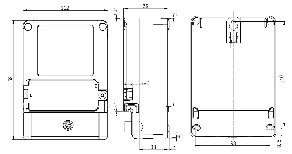
158mm×112mm×58mm
Operating life
>10 years
Relative humidity
Generally not greater than 85% RH.
Within 30 days of a year(naturally distributed), sometimes reaching 95% RH.
Working Principle
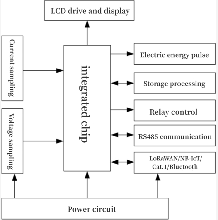
The voltage/current sampling circuit samples the voltage of the power grid and the current flowing through the energy meter.The sampled voltage and current signals are multiplied to obtain the power value, which is then integrated over time to obtain the electrical energy.And smart energy meters measure electrical energy by counting the output CF pulses. After correcting the error through an energy meter, simply count the CF pulse to obtain the electrical energy, which save electrical energy through storage. The microprocessor performs both display and external information exchange functions.

Schematic diagram
Operation, Adjustment, and Installation
· The electricity meter does not require corresponding operation and adjustment by the user after leaving the factory. According to the installation wiring diagram, it can only be used after being installed by professional personnel.
Before installing the electric energy meter, check the lead seal of the manufacturer and ensure that it is in good condition before starting the installation.
· The energy meter should be installed on a sturdy fire-resistant wall indoors or outdoors, with a height of approximately 1.8m. There is no corrosive gas in the air.
· The electricity meter should be wired according to the wiring diagram shown in the manual. It is best to use copper wire or copper wire connector to connect, and each wiring terminal must be tightened.
Wiring Method

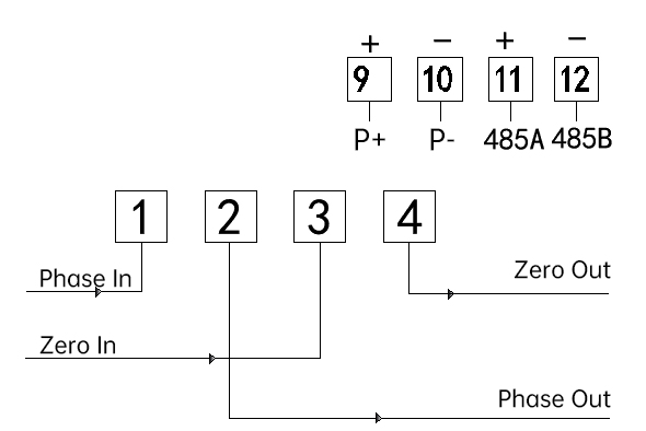
The main terminal wiring is shown in Figure 2. Among them, 1 is the phase line in, 2 is the phase line out, 3 is the zero line in, and 4 is the zero line out. There are 4 auxiliary terminals above the main terminals of the energy meter. Among them, 9 and 10 are metering pulse output, and 11 and 12 are 485 communication.
Display Description
After powering on, the LCD screen will fully display for 3 seconds. Then display the current active electrical energy and current active power alternately.

RS485 Communication Interface
· The RS485 interface must be electrically isolated from the internal circuit of the energy meter and effectively protect the circuit.
· The RS485 interface should meet the electrical requirements of DL/T 645-2007. And can withstand an AC voltage of 380V for 2 minutes without damage.
· The communication rate of the RS485 interface can be set. The standard speeds are 1200bps, 2400bps, 4800bps, and 9600bps. The default value is 2400bps.
LoRaWAN/NB-IoT Communication interface (optional)
· Interface communication rate is 9600bps, even parity check, 8-bit data bit
· Interface communication follows DL/T 645-2007 protocol and its filing documents
· After 10 seconds of powering on the electricity meter, communication can be carried out using the LoRaWAN/NB IoT interface.
· Active upload/bidirectional transparent transmission function: Actively upload data. The default interval for uploading data is 4 hours (the time can be set).
External dimensions (unit:mm)

You may like
-
 Online service
-
 Hotline
-
 WhatsApp
-


